Rotordynamics Challenges in High-Speed Compact Turbomachinery

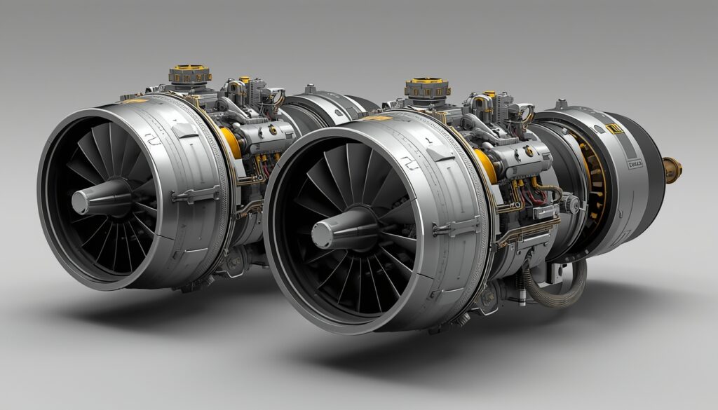
Back to Blog Turbomachinery Rotordynamics Challenges in High-Speed Compact Turbomachinery CTO, Dheya Engineering Technologies Private limited dev March 13, 2026 6:03 am Introduction High-speed compact turbomachinery—encompassing microturbines, turbochargers, cryogenic turbopumps, turboexpanders, and miniaturized power generation systems—operates under extreme conditions that challenge conventional Rotordynamics design principles. These machines routinely achieve rotational speeds ranging from 100,000 to over 240,000 rpm, with cutting-edge MEMS-scale devices reaching 1.7 million rpm. At such velocities, rotor tip speeds approach transonic conditions, centrifugal stresses reach material limits, and dynamic phenomena that remain benign in larger, slower machinery become critical failure mechanisms requiring sophisticated analysis and mitigation strategies. The trend toward compact, high-power-density turbomachinery across aerospace, industrial, and emerging energy applications intensifies rotordynamic challenges. Miniaturization imposes adverse scaling effects: bearing stiffness-to-rotor-mass ratios deteriorate, clearances become proportionally larger relative to component dimensions, thermal gradients steepen, and manufacturing tolerances tighten. Simultaneously, operational demands escalate—higher pressure ratios, elevated temperatures, extended operating envelopes—while reliability expectations remain uncompromising. Understanding and addressing the constellation of rotordynamic challenges inherent to these demanding applications represents a critical frontier in turbomachinery development, directly impacting performance, durability, and commercial viability. Critical Speed Management and Resonance Avoidance Fundamental Critical Speed Considerations Critical speeds—rotational velocities at which rotor natural frequencies coincide with operating frequencies, producing mechanical resonance—represent perhaps the most fundamental rotordynamic design constraint for high-speed machinery. Traditional design philosophy advocates placing critical speeds at least 15-20% away from the operating speed range to avoid sustained resonant operation that amplifies vibrations and accelerates fatigue damage. However, compact high-speed turbomachinery frequently operates above the first, and sometimes second, bending critical speeds due to the practical impossibility of elevating critical speeds sufficiently through stiffness modifications alone. A representative turboexpander rotor designed for 240,000 rpm operation exhibits first and second critical speeds at approximately 60,000 rpm and 120,000 rpm respectively—well within the startup transient pass-through envelope. This necessitates “supercritical” rotor design where the machine routinely operates above one or more critical speeds, relying on adequate bearing damping and controlled acceleration through resonant zones to limit vibration amplitudes. The challenge intensifies in compact machines where rotor flexibility increases relative to bearing stiffness, creating lower critical speeds and narrower separation margins between successive modes. The relationship between bearing support stiffness and critical speed placement reveals complex design trade-offs. Increasing bearing stiffness elevates second and higher critical speeds but may inadvertently lower the first critical speed or reduce separation between modes, potentially worsening vibration response. For rolling element bearings commonly employed in compact turbomachinery, relatively flexible mounting structures introduce additional compliance that must be modeled accurately—neglecting foundation flexibility can underpredict resonance amplitudes by factors of 10×, leading to catastrophic design errors. Proper critical speed management demands coupled rotor-bearing-foundation analysis incorporating all significant compliance sources and validation through modal testing. Campbell Diagrams and Mode Shape Analysis Campbell diagrams—plotting natural frequencies versus rotational speed and identifying intersections between operating speed lines and natural frequency curves—provide essential visualization tools for critical speed identification and resonance risk assessment. For high-speed compact rotors, these diagrams reveal not only the primary bending modes but also complex coupled torsional-lateral modes, whirl instabilities, and parametric excitation phenomena that can produce subharmonic and super harmonic resonances at fractional or multiple operating speeds. Mode shape analysis accompanying critical speed prediction identifies nodal patterns and maximum deflection locations, informing bearing placement optimization, disk positioning, and structural reinforcement strategies. In compact turbomachinery with closely spaced impellers and limited axial length, achieving favorable mode shapes that minimize bearing loads and avoid excessive disk deflections becomes particularly challenging. The first bending mode typically exhibits a single antinode, while second and higher modes introduce multiple antinodes that can produce localized stress concentrations requiring detailed finite element analysis for fatigue assessment. Damping Deficiency and Instability Mechanisms Inadequate Damping in Compact Systems Damping—the mechanism dissipating vibrational energy and controlling resonant amplitude—proves critically deficient in many high-speed compact turbomachinery designs. Rolling element bearings, favored for their compact size, high stiffness, and speed capability, provide minimal inherent damping. Measured damping ratios in rolling element bearing systems typically range from 0.5-2%, compared to 10-30% achievable with properly designed fluid film bearings. This damping deficiency renders compact machines highly susceptible to resonance amplification, requiring conservative critical speed separation margins and potentially limiting achievable power density. The situation worsens at elevated speeds where aerodynamic cross-coupling forces generated by impeller-shroud interactions, labyrinth seals, and volute asymmetries introduce destabilizing influences that can overcome available damping and trigger self-excited instabilities. These rotor instabilities—characterized by sub synchronous vibrations at natural frequencies independent of external forcing—can produce vibration amplitudes orders of magnitude larger than those from residual imbalance, leading to bearing failure, seal rubs, and catastrophic rotor failure. Gas foil bearings, increasingly employed in oil-free compact turbomachinery applications, offer improved damping through Coulomb friction mechanisms at foil interfaces but introduce nonlinear amplitude-dependent characteristics complicating dynamic prediction. The damping effectiveness depends on bearing preload, compliance structure design, operating temperature, and wear condition—parameters subject to manufacturing variability and operational degradation. Achieving reliably adequate damping across all operating conditions and throughout machine life remains an active research challenge requiring careful bearing specification, validation testing, and often incorporation of supplementary damping elements such as squeeze film dampers or viscoelastic supports. Internal Damping Instability An insidious instability mechanism particularly relevant to high-speed compact rotors operating super critically involves internal material damping and joint friction within the rotor structure itself. Counterintuitively, internal damping—generally considered beneficial for vibration suppression—becomes destabilizing for rotors operating above the first bending critical speed. This paradoxical behavior arises because internal damping forces act in phase with rotor deflection velocity in the rotating reference frame, producing negative work per cycle that extracts energy from external damping mechanisms. Experimental investigations on representative high-speed turbomachinery rotors with splined joints and interference fit connections demonstrate severe sub synchronous instabilities at frequencies corresponding to the first natural frequency when operated super critically. Testing of rotors with axial spline joints under 5,000 in-lb torque revealed “extremely severe instability” in the supercritical regime, validating nonlinear time-transient predictions. The coefficient of friction at material interfaces—approximately 0.2 for lubricated and 0.8 for unlubricated
Micro Turbojets for Expendable Targets: Opportunities & Challenges
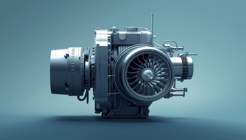
Back to Blog Turbomachinery Micro Turbojets for Expendable Targets: Opportunities & Challenges CTO, Dheya Engineering Technologies Private limited dev March 13, 2026 6:01 am Introduction The global target drone market, valued at USD 4.69 billion in 2026 and projected to reach USD 8.62 billion by 2034, represents a rapidly expanding segment of the defense industry driven by evolving aerial threats and modernization of military training infrastructure. At the heart of many advanced target drone systems lies a critical propulsion technology: the micro turbojet engine. These compact powerplants, typically delivering thrust ranges from 200N to 1,500N, enable target drones to accurately simulate cruise missiles, loitering munitions, and hostile aircraft in realistic training scenarios. As armed forces worldwide seek cost-effective alternatives to expending live ammunition against expensive manned aircraft, the development and deployment of expendable micro turbojets have emerged as both a compelling market opportunity and a complex engineering challenge. The term “expendable” fundamentally reshapes traditional aerospace engineering priorities. Unlike engines designed for thousands of hours of operation and multiple maintenance cycles, expendable turbojets prioritize simplicity, reliability, and above all—affordability. This philosophical shift creates unique opportunities for innovative design approaches, advanced manufacturing techniques, and new market entrants, while simultaneously presenting formidable technical challenges related to performance optimization within severe cost constraints. Understanding this opportunity-challenge dynamic is essential for stakeholders across the defense supply chain, from prime contractors to specialized propulsion developers. Market Opportunities: A Growing Defense Priority Expanding Global Demand and Market Drivers The target drone market’s robust 7.93% compound annual growth rate through 2034 reflects several converging factors that create substantial opportunities for micro turbojet manufacturers. Military segments dominate the market with 93.31% share, driven by the need for realistic threat simulation in an era of increasingly sophisticated aerial weapons. Modern air defense crews must train against supersonic cruise missiles, stealthy unmanned systems, and coordinated drone swarms—threats that traditional towed targets and subsonic drones cannot adequately represent. North America leads global demand, accounting for 42.19% of market share in 2025, with the U.S. market alone projected to reach USD 1.8 billion by 2026[1]. The U.S. Navy’s expanded use of the BQM-177A target drone and similar programs demonstrate sustained institutional commitment to jet-powered expendable targets. European markets are accelerating rapidly following the Russia-Ukraine conflict, with NATO members expanding training programs to address heightened security concerns. The U.K.’s procurement of additional Banshee Jet 80+ target drones exemplifies this trend. Emerging opportunities exist in the lightweight category, where drones under 25kg dominate with 46.45% market share due to their cost-effectiveness and deployment simplicity. This segment creates specific opportunities for ultra-compact micro turbojets in the 200-500N thrust class, suitable for high-volume gunnery training and short-range missile exercises. The relatively lower manufacturing costs and faster deployment cycles enable armed forces to conduct realistic training at scale without prohibitive operational expenses. Indigenous Development and Strategic Autonomy National defense priorities are increasingly driving indigenous micro turbojet development programs, creating opportunities for domestic manufacturers to capture market share previously dominated by foreign suppliers. India’s partnership between Larsen & Toubro (L&T) and Green Aero represents a strategic initiative to develop domestic micro turbojet capabilities, reducing import dependency and establishing local supply chains. Such partnerships leverage established engineering capabilities with specialized aerospace R&D to accelerate technology transfer and manufacturing scale-up. The strategic autonomy rationale extends beyond immediate cost savings. Domestic production secures supply chains against geopolitical disruptions, enables export opportunities to allied nations, and develops critical aerospace competencies that can be leveraged across broader defense and commercial applications. For developing aerospace nations, expendable micro turbojets represent a more accessible entry point than large commercial engines, requiring lower capital investment while building foundational turbomachinery expertise. Technology Integration and Advanced Capabilities Modern target drones are evolving beyond simple speed-altitude profiles toward sophisticated threat emulation incorporating radar cross-section enhancement, infrared signature simulation, and autonomous maneuvering. This evolution creates opportunities for micro turbojet manufacturers to integrate complementary technologies—electrical power generation for onboard systems, vectored thrust for enhanced agility, and adaptive control for variable flight profiles. The PBS TJ80 and TJ100 series engines, featuring integrated 750W generators and compact designs, exemplify this integration trend. The convergence with autonomous and AI-driven control systems presents additional opportunities. As target drones incorporate more sophisticated mission planning and adaptive behaviors, propulsion systems must provide responsive throttle control, precise thrust modulation, and seamless integration with flight management systems. Manufacturers that can deliver “smart” propulsion packages—combining engine hardware with advanced control algorithms and health monitoring—position themselves favorably against competitors offering commoditized hardware alone. Technical Challenges: Engineering for Expendability Performance-Cost Trade-offs and Design Philosophy The fundamental challenge in expendable turbojet development lies in achieving acceptable performance within stringent cost constraints that may be one-tenth those of conventional aerospace engines. The design philosophy for expendable engines—”simple, reliable, and cheap are higher demands than performance”—represents a radical departure from traditional turbomachinery development. This paradigm shift affects every aspect of the design process, from material selection to manufacturing tolerances to testing protocols. Achieving thrust-to-weight ratios competitive with conventional small turbojets while maintaining expendable cost targets demands innovative approaches. Chinese manufacturers have demonstrated ceramic matrix composite (CMC) turbine disks achieving instantaneous thrust of 25daN (250N) with turbine inlet temperatures reaching 1,400K, enabling substantial performance gains while controlling costs through reduced cooling requirements. However, CMC manufacturing at scale remains challenging, particularly for high-volume expendable applications where per-unit cost dominates design decisions. The performance envelope must satisfy diverse mission requirements—cruise speeds of 400-500 km/h for realistic threat simulation, altitude capabilities to 3,000-4,000 meters, and endurance of 60+ minutes for extended training scenarios. Meeting these specifications with simplified single-shaft configurations, reduced component counts, and relaxed manufacturing tolerances requires careful optimization of thermodynamic cycles and component efficiencies. As one technical analysis notes, the low working efficiency of components and short service life remain primary constraints on domestic micro turbojet performance. Manufacturing Challenges and Production Economics Traditional aerospace manufacturing processes—precision casting, multi-axis CNC machining, and extensive quality assurance—deliver superb performance but generate cost structures incompatible with expendable applications. Achieving economically viable production requires manufacturing innovations that dramatically reduce per-unit costs without
Hydrogen-Based Micro Turbo Generators for Distributed and Remote Power Generation: Adaptation and Developmental Challenges
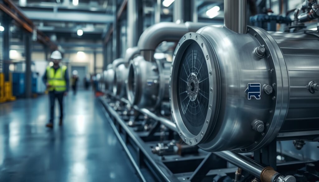
Back to Blog Turbomachinery Hydrogen-Based Micro Turbo Generators for Distributed and Remote Power Generation: Adaptation and Developmental Challenges CTO, Dheya Engineering Technologies Private limited dev March 13, 2026 5:58 am Introduction Hydrogen-fueled micro turbo generators—compact gas turbine systems delivering electrical power outputs between 3-300 kW—represent an emerging solution for distributed and remote power generation applications where reliability, rapid load response, and emissions reduction converge as critical requirements. These miniaturized thermodynamic engines offer compelling advantages over diesel generators traditionally deployed in telecommunications sites, remote facilities, and backup power installations: zero carbon dioxide emissions when fueled with green hydrogen, fuel flexibility enabling operation across hydrogen-natural gas blends, superior power density compared to fuel cells, and rapid response to load transients supporting renewable energy integration. As global energy systems transition toward decarbonization and distributed generation architectures, hydrogen micro turbines occupy a strategic niche between stationary fuel cells optimized for steady-state efficiency and conventional diesel gensets constrained by emissions and fuel logistics. However, adapting gas turbine technology—originally developed for natural gas and liquid hydrocarbon combustion—to hydrogen fuel presents formidable technical challenges spanning combustion system redesign, materials compatibility, fuel supply infrastructure, and system-level integration. Hydrogen’s combustion characteristics differ fundamentally from natural gas: laminar flame speed 7-8 times higher (2.0-3.0 m/s versus 0.37 m/s), density one-ninth that of methane creating volumetric flow challenges, lower energy density per unit volume demanding larger fuel systems, and propensity for flashback where flames propagate upstream into fuel-air mixing zones risking hardware damage. These property differences necessitate extensive redesign rather than simple fuel substitution, particularly in compact geometries where miniaturization amplifies sensitivity to combustion instabilities and sealing challenges. The developmental pathway for hydrogen micro turbo generators confronts interrelated obstacles: combustion system adaptation preventing flashback while controlling nitrogen oxide (NOx) emissions, thermodynamic cycle modifications accommodating reduced fuel density and altered combustion characteristics, materials selection resisting hydrogen embrittlement in high-stress components, fuel supply infrastructure establishing hydrogen availability in remote locations, and economic viability demonstrating lifecycle cost competitiveness against incumbent diesel and emerging battery-electrolyzer alternatives. This document examines these multifaceted challenges systematically, drawing from recent research, manufacturer experience, and demonstration projects to provide engineering teams with actionable insights for advancing hydrogen micro turbine technology from laboratory demonstrations toward commercial viability in distributed power applications. Combustion System Adaptation Challenges Flashback Prevention and Flame Stabilization The paramount combustion challenge facing hydrogen micro turbines stems from hydrogen’s exceptionally high laminar flame speed—2.0-3.0 m/s for pure hydrogen versus 0.37 m/s for natural gas—creating severe flashback risk where flames propagate upstream through fuel-air mixing passages into fuel manifolds, potentially causing catastrophic hardware damage. Flashback occurs when local flow velocities fall below flame propagation speed, allowing reaction zones to migrate toward fuel injectors. Experimental investigations on micromixer-based burners reveal that flashback initiation consistently occurs at adiabatic flame temperatures near 1800 K, with two distinct flashback modes observed: acoustic fluctuations preceding actual flame propagation (flashback mode 1), followed by physical flame migration into mixing zones (flashback mode 2). Compact combustor geometries exacerbate flashback susceptibility because shortened mixing lengths and reduced flow velocities—dictated by miniaturized dimensions and lower mass flow rates—provide less margin between operating flow velocities and critical flashback thresholds. Conventional swirl-stabilized combustors employing central recirculation zones create low-velocity regions vulnerable to flashback when hydrogen content exceeds 30-50% by volume. Current micro gas turbines typically achieve only 20-30% hydrogen blending capability with conventional combustors before encountering flashback limits, far below the 100% hydrogen operation required for zero-carbon applications. Advanced combustion approaches mitigating flashback risk include: jet-stabilized burners creating high-velocity fuel-air injection suppressing upstream flame propagation, micromixer configurations employing numerous small-scale mixing elements maintaining high local velocities, lean premixed combustion strategies operating at low equivalence ratios reducing flame temperatures and propagation speeds, and sequential combustion systems separating hydrogen injection from primary reaction zones. The German Aerospace Center (DLR) demonstrated successful flashback suppression through jet-stabilized burner technology, achieving 100 hours of stable operation on pure hydrogen in a 100-kW micro turbine, with controlled exhaust gas recirculation lowering combustion temperatures and stabilizing flames across full load range. Nitrogen Oxide Emissions Control While hydrogen combustion eliminates carbon-based emissions, thermal nitrogen oxide (NOx) formation remains a critical environmental concern, as high combustion temperatures (above 1800 K) promote thermal NOx generation through oxidation of atmospheric nitrogen via the Zeldovich mechanism. NOx emissions from hydrogen combustion can exceed natural gas levels when operating at stoichiometric or near-stoichiometric conditions due to elevated flame temperatures resulting from hydrogen’s higher heating value per unit mass and faster reaction kinetics. Regulatory limits for distributed generation applications typically mandate NOx emissions below 15-25 ppm (corrected to 15% O₂), with emerging standards targeting single-digit ppm levels matching ultra-low-emission natural gas turbines. Lean premixed combustion represents the primary NOx control strategy, operating at equivalence ratios of 0.4-0.6 to reduce peak flame temperatures below thermal NOx formation thresholds while maintaining combustion stability. Experimental characterization demonstrates that lean cold combustion conditions successfully reduce NOx emissions to single-digit ppm levels (below 10 ppm) even at high adiabatic flame temperatures, though operational windows narrow as hydrogen fraction increases, requiring precise fuel-air ratio control. Dilution strategies employing exhaust gas recirculation, steam injection, or nitrogen dilution further suppress NOx formation by reducing oxygen concentration and peak temperatures, with recent demonstrations achieving sub-5 ppm NOx emissions at full load through optimized dilution combined with lean combustion. However, lean operation trades NOx reduction against combustion stability degradation, as lower equivalence ratios increase blowout risk and amplify sensitivity to inlet condition variations. Micro-scale combustors experience heightened stability challenges due to increased surface-to-volume ratios promoting heat losses and reduced residence times limiting reaction completion. The operational envelope between lean blowout (lower stability boundary) and flashback (upper stability boundary) narrows significantly with increasing hydrogen content, demanding sophisticated combustion control systems maintaining precise fuel-air ratios across transient load conditions. Computational optimization of combustor geometry, fuel injection patterns, and mixing characteristics proves essential for expanding stable operating ranges while achieving emissions compliance. Combustor Design Requirements and Material Considerations Hydrogen combustor design for micro turbines demands geometric modifications addressing flame speed, temperature distribution, and structural durability within
Hydrogen Anode Blowers for Air Independent Propulsion Systems
Back to Blog Turbomachinery Hydrogen Anode Blowers for Air Independent Propulsion Systems CTO, Dheya Engineering Technologies Private limited dev March 13, 2026 5:56 am Introduction Air Independent Propulsion (AIP) systems represent a transformational advancement in submarine technology, enabling non-nuclear submarines to operate submerged for extended periods without accessing atmospheric oxygen. At the heart of modern fuel cell-based AIP systems lies a critical but often overlooked component: the hydrogen anode recirculation blower. This sophisticated piece of equipment plays a pivotal role in optimizing fuel cell efficiency, enhancing underwater endurance, and ensuring the tactical superiority of contemporary submarine platforms. Unlike traditional diesel-electric submarines that must surface or snorkel frequently to recharge batteries, AIP-equipped vessels can remain submerged for weeks at a time, dramatically improving their stealth characteristics and operational effectiveness. Among the various AIP technologies—including Stirling engines, closed-cycle diesel, and closed-cycle gas turbines—fuel cell systems have emerged as particularly promising due to their silent operation, minimal thermal signature, and high efficiency. Central to these fuel cell systems is the anode blower, which manages hydrogen recirculation and ensures optimal electrochemical reactions within the fuel cell stack. The Role of Hydrogen Anode Blowers in Fuel Cell Systems Fundamental Operating Principles Fuel cells generate electrical power through an electrochemical reaction between hydrogen and oxygen, producing water and electricity without combustion. In the anode path of a Proton Exchange Membrane (PEM) or Phosphoric Acid Fuel Cell (PAFC) system, hydrogen is supplied to the anode side of the fuel cell stack. However, not all hydrogen is consumed during the electrochemical reaction due to operational surplus requirements that maintain system stability and prevent cell starvation. The hydrogen anode recirculation blower addresses this inefficiency by actively returning unconsumed hydrogen from the stack outlet back to the inlet, mixing it with fresh hydrogen supply. This recirculation serves multiple critical functions: it ensures uniform hydrogen distribution across all cells in the stack, improves start-up behavior, enhances overall system efficiency, and reduces hydrogen consumption by up to 20% compared to once-through systems. Technical Configuration and Design Considerations Modern anode recirculation blowers for AIP applications typically feature compact, highly integrated designs that minimize installation space and weight—crucial considerations in the space-constrained submarine environment. Leading manufacturers such as Bosch, ZF, and specialized marine equipment suppliers have developed blowers utilizing advanced electric motor technologies, including media-gap motors that eliminate the need for active cooling and integrate water separation directly within the device. The blower operates in conjunction with passive ejector systems (jet pumps) to create a hybrid recirculation architecture. At low power demands, the passive jet pump may suffice, but as power requirements increase, the active blower ensures adequate hydrogen flow rates and pressure maintenance. Control is typically achieved via CAN-bus interfaces integrated with the fuel cell control system, enabling precise flow modulation based on real-time power demand and stack conditions. Critical design parameters include: Media compatibility with high-purity hydrogen and moisture management Explosion-proof construction meeting ATEX or IECEx standards for hazardous atmospheres Low acoustic signature to maintain submarine stealth characteristics High reliability and minimal maintenance requirements for extended underwater operations Efficient water management to handle condensate in the anode path Application in Naval AIP Systems Current Implementations and Naval Programs Several navies worldwide have successfully deployed or are developing fuel cell-based AIP systems featuring advanced anode recirculation technologies. The German Navy’s Type 212 and 214 submarines, equipped with HDW fuel cell systems, pioneered operational fuel cell AIP, storing liquid hydrogen and liquid oxygen (LOX) onboard to achieve underwater endurance exceeding two weeks. These systems employ sophisticated blower technologies to maximize hydrogen utilization efficiency. India’s Defence Research and Development Organization (DRDO) has developed an indigenous fuel cell AIP system for the Kalvari-class submarines, utilizing PAFC technology with onboard sodium borohydride (NaBH₄) hydrolysis for hydrogen generation. The system incorporates dedicated anode and cathode recirculation blowers that return unreacted gases to the fuel cell stacks after moisture removal, with oxygen injection controlled based on concentration measurements in the recirculation loop. While initially targeted for 2025 installation, ground testing continues to validate system performance and integration requirements. Spain’s Navantia has advanced third-generation AIP technology for the S-80 Plus submarine class, featuring on-demand hydrogen generation rather than stored hydrogen. This approach provides tactical and safety advantages by eliminating the hazards associated with storing large quantities of compressed or liquid hydrogen, while the integrated anode blower system ensures efficient hydrogen management throughout varying power demands. Performance Enhancement and Operational Benefits Recent computational studies demonstrate the substantial advantages of optimized anode recirculation systems in AIP applications. A 2025 study utilizing Mamdani-style fuzzy logic control for power allocation in hydrogen-based AIP systems revealed a 53% improvement in underwater endurance compared to conventional diesel-electric propulsion, alongside a 20% reduction in fuel consumption. These gains result from intelligent hydrogen management, where the anode blower plays a crucial role in maintaining optimal stoichiometric ratios and preventing hydrogen waste. The recirculation blower also serves critical auxiliary functions during start-up and shutdown sequences. During cold starts, the blower provides anode path conditioning by purging inert gases and establishing proper hydrogen concentration before power generation commences. During shutdown, it facilitates safe purging to prevent hydrogen accumulation and ensure system readiness for subsequent operations. These functions are particularly important in submarine applications where rapid response to changing tactical situations is essential. Technical Challenges and Future Developments Integration and Reliability Considerations Integrating hydrogen anode blowers into submarine AIP systems presents unique challenges. The marine environment demands exceptional reliability, as maintenance opportunities are extremely limited during extended patrols. Blowers must operate flawlessly in conditions ranging from tropical surface temperatures to near-freezing deep-water environments, while managing hydrogen purity, moisture content, and pressure variations. Acoustic signature management represents another critical challenge. Submarines depend on stealth for survival, and any rotating machinery introduces potential noise sources. Advanced bearing technologies, magnetic coupling drives, and vibration isolation systems are employed to minimize the acoustic footprint of anode recirculation blowers. Some designs incorporate variable speed control algorithms that optimize flow rates while maintaining the lowest possible rotational speeds consistent with system demands. Water management within the
Challenges in Developing High-Efficiency Centrifugal Compressors for Compact Turbomachinery Solutions
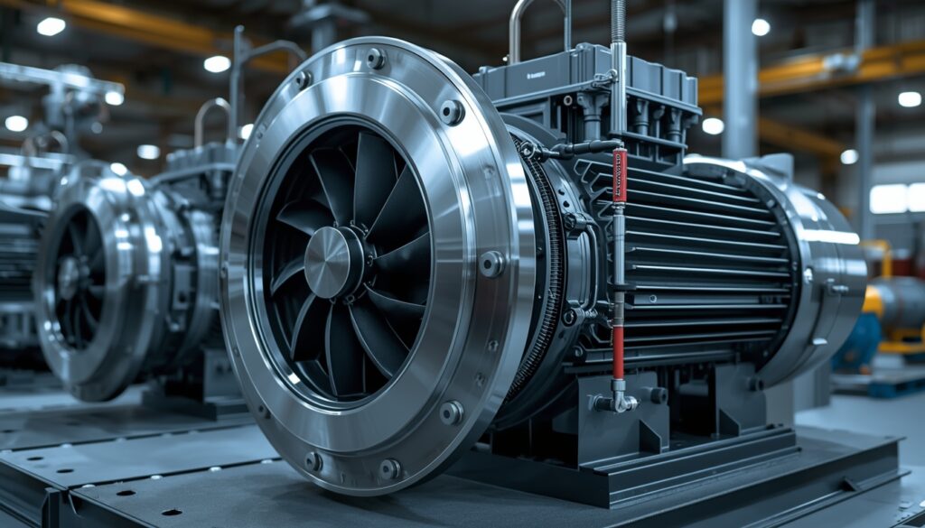
Back to Blog Turbomachinery Challenges in Developing High-Efficiency Centrifugal Compressors for Compact Turbomachinery Solutions CTO, Dheya Engineering Technologies Private limited dev March 13, 2026 5:53 am Introduction Centrifugal compressors serve as the aerodynamic heart of compact turbomachinery systems spanning micro gas turbines, turbochargers, auxiliary power units, refrigeration compressors, and fuel cell air supply systems. These radial-flow machines convert kinetic energy imparted by high-speed rotating impellers into static pressure through diffusion, achieving pressure ratios of 3:1 to 8:1 per stage in footprints dramatically smaller than equivalent axial compressor configurations. As applications increasingly demand higher power densities, broader operating ranges, and improved fuel economy, the pressure intensifies to extract maximum efficiency from progressively smaller centrifugal compressor geometries. However, the physics of miniaturization proves unforgiving: as impeller diameters shrink below 100 mm and rotational speeds exceed 100,000 rpm, a constellation of adverse scaling effects conspire to degrade performance, with micro-scale compressors (impeller diameters <30 mm) achieving efficiencies 15-25 percentage points lower than their larger counterparts. The efficiency challenge manifests across multiple coupled domains: aerodynamic losses intensify due to Reynolds number effects and relative geometric constraints, mechanical design limitations constrain achievable geometries, manufacturing precision requirements tighten as tolerances scale disproportionately, and operational stability margins narrow as surge and choke boundaries converge. Unlike large industrial compressors where incremental efficiency improvements of 0.5-1.0% justify substantial development investments, compact turbomachinery must overcome fundamental 10-15% efficiency deficits before reaching competitive performance levels. This context transforms centrifugal compressor development for compact applications from an optimization exercise into a multi-physics challenge requiring simultaneous advances in aerodynamic design, precision manufacturing, material science, and rotordynamic integration. Understanding these interrelated challenges and the emerging solutions represents critical knowledge for engineers pursuing the next generation of high-efficiency compact turbomachinery. Aerodynamic Loss Mechanisms in Compact Geometries Reynolds Number Effects and Viscous Loss Amplification The most pervasive performance degradation mechanism affecting compact centrifugal compressors stems from operation at low Reynolds numbers where viscous forces dominate inertial forces, thickening boundary layers and amplifying friction losses throughout the flow path. Reynolds number—the dimensionless ratio of inertial to viscous forces—scales linearly with characteristic dimensions and velocities while inversely with kinematic viscosity. As compressor scale decreases, achieving Reynolds numbers above the critical threshold of approximately 200,000 (where boundary layer transition to turbulence occurs and viscous losses stabilize) becomes progressively difficult without resorting to extremely high rotational speeds or elevated operating pressures. Experimental characterization of micro-scale centrifugal compressors reveals severe efficiency penalties at Reynolds numbers below 100,000, with losses increasing inversely proportional to Reynolds number following relationships derived from pipe flow friction correlations. Analytical models suggest that approximately 70% of Reynolds-dependent losses correlate with viscous effects, with the remaining 30% representing Reynolds-independent contributions from incidence losses, secondary flows, and flow separation. The narrowest flow passages—typically at impeller outlet where blade height reaches minimum values—experience the most severe viscous penalties, as boundary layer thickness becomes comparable to passage dimensions creating substantial blockage and degrading effective flow area. Computational fluid dynamics (CFD) investigations quantifying individual loss mechanisms in micro-scale impellers demonstrate that friction losses between fluid and casing surfaces increase dramatically at high mass flow rates where elevated velocities amplify shear stresses, while secondary flow losses dominate at low mass flows where strong velocity gradients perpendicular to primary flow direction generate cross-channel vorticity. The viscous sublayer in laminar or transitional boundary layers exhibits velocity profiles fundamentally different from turbulent cases, producing higher skin friction coefficients and increased sensitivity to surface roughness. Relative surface roughness—the ratio of surface irregularity height to passage hydraulic diameter—grows disproportionately as dimensions shrink, further exacerbating viscous losses in micro-scale geometries. Mitigation strategies addressing Reynolds number effects include: operating at elevated pressures increasing air density and consequently Reynolds number without speed increases, surface finishing achieving mirror-polish blade and shroud surfaces minimizing roughness contributions, and design optimization at representative low Reynolds numbers rather than extrapolating from large-scale compressor correlations developed for fully turbulent flows. However, fundamental thermodynamic constraints limit achievable improvements, as scaling laws dictate that below certain size thresholds, practical Reynolds numbers cannot reach regimes where efficiency approaches large-compressor values regardless of design sophistication. Tip Clearance Losses and Scaling Penalties Tip clearance—the radial gap between impeller blade tips and stationary shroud surfaces—represents a critical loss mechanism in centrifugal compressors, permitting high-pressure fluid on blade pressure surfaces to leak across blade tips to low-pressure suction surfaces without performing useful compression work. This leakage flow generates complex three-dimensional vortical structures that mix with the main passage flow, dissipating kinetic energy while creating blockage that reduces effective flow area and degrades performance. Extensive experimental and numerical research characterizes tip clearance sensitivity: each 1% increase in clearance ratio (tip gap divided by blade exit height) produces approximately 0.35-0.45 percentage point reduction in isentropic efficiency at design speed, with sensitivities varying across the operating envelope and peaking during transonic operation. The scaling penalty for compact compressors arises because absolute manufacturing tolerances—determined by machining capabilities, thermal expansion uncertainties, and assembly stack-up variations—do not scale proportionally with machine size. A 0.1 mm tip clearance may represent just 1% of blade height in a 150 mm diameter impeller but constitutes 5-10% in a 30 mm micro-scale design, amplifying leakage losses five to tenfold. Manufacturing tolerances tighten dramatically for small impellers: achieving clearance ratios below 2-3% in micro-scale designs demands tolerances of ±0.02 mm or tighter, approaching limits of conventional machining and assembly processes. Computational studies on micro gas turbine centrifugal compressors demonstrate that increasing tip clearance from 0.2 mm to 1.0 mm in a 30 mm diameter impeller produces efficiency degradation exceeding 10 percentage points, with leakage mass flow reaching 15-20% of inlet flow at the largest clearances. The leakage jet emerging from the clearance gap interacts with the main passage flow creating tip leakage vortices that propagate downstream into the diffuser, disturbing pressure recovery and potentially triggering diffuser stall at operating points where the compressor would otherwise remain stable. Clearance sensitivity exhibits complex dependencies on blade loading, impeller rotational speed, and flow coefficient, with maximum loss generation occurring at intermediate mass flows where pressure differentials
Air Foil Bearings Developments
Back to Blog Turbomachinery Air Foil Bearings for Oil-Free Turbomachinery: Development Challenges CTO, Dheya Engineering Technologies Private limited dev March 13, 2026 5:39 am Introduction Air foil bearings, also known as gas foil bearings or compliant foil bearings, represent a transformative technology enabling oil-free operation of high-speed turbomachinery across diverse applications—from aircraft cabin pressurization systems to microturbine generators, cryogenic turbopumps, and turbochargers. These self-acting hydrodynamic bearings utilize ambient air or process gas as their lubricant, eliminating the complexity, maintenance burden, and contamination risks associated with oil-lubricated systems. During operation, shaft rotation drags fluid into the bearing clearance through viscous action, creating a pressurized lubricating film that separates compliant foil surfaces from the rotating shaft while supporting operational loads. Despite their compelling advantages—maintenance-free operation, extreme temperature capability (cryogenic to 650°C+), high-speed capacity exceeding 100,000 rpm, and remarkable durability—air foil bearings face substantial technical challenges that have historically limited their adoption to lower-power applications, typically below 500 kW. The past two decades have witnessed intensive research and development efforts aimed at overcoming fundamental limitations related to load capacity, damping characteristics, thermal management, start-stop durability, and manufacturing complexity. As turbomachinery designers increasingly seek oil-free solutions for megawatt-class systems and harsh operating environments, understanding these development challenges becomes critical for advancing foil bearing technology toward broader commercial deployment. Fundamental Design Challenges Load Capacity and Stiffness Limitations The most significant barrier preventing widespread adoption of air foil bearings in high-power turbomachinery is insufficient load-carrying capacity compared to conventional oil-lubricated or rolling element bearings. The load capacity challenge stems from fundamental physics: gas lubricants possess viscosities approximately 1,000 times lower than oil, generating proportionally thinner lubricating films and lower hydrodynamic pressures. While compliant foil structures partially compensate by conforming to shaft deflections and distributing loads more uniformly, achieving adequate stiffness for megawatt-class applications remains problematic. Recent numerical investigations on gas foil journal bearings designed for cryogenic LH₂ turbopump applications (50.8 mm diameter, 38,000 rpm, 2,000 N radial load) reveal the complex interplay between bearing parameters and load capacity. Parametric studies demonstrate that stiffness increases with bearing number (dimensionless speed-load parameter) but decreases with increased bearing compliance—creating an inherent design trade-off between conformability and structural rigidity. Further complicating matters, stiffness coefficients increase while damping coefficients decrease at higher speeds, requiring careful optimization to maintain adequate dynamic performance across the operational envelope. Advanced foil bearing designs have incorporated several innovations to enhance load capacity. Generation III bearings developed for oil-free turbochargers employ optimized foil geometries, improved preload strategies, and refined compliant structures that significantly outperform earlier designs. Modular thrust bearing architectures facilitate parametric evaluation of various configurations without extensive redesign, enabling rapid design iterations. However, extending these improvements from sub-500 kW applications to multi-megawatt turbomachinery requires substantial additional development to achieve the 5-10× load capacity increases necessary for competitive performance. Damping and Dynamic Stability Adequate damping represents the second critical hurdle for foil bearing technology penetration into high-power applications. Damping in foil bearings arises primarily from Coulomb (dry friction) mechanisms at interfaces between compliant foils and backing structures, supplemented by hydrodynamic effects in the gas film. While this combination provides reasonable damping for small-to-medium machines, the nonlinear and amplitude-dependent nature of friction damping complicates dynamic analysis and creates challenges for rotordynamic prediction and stability assurance. The nonlinear coupling between rotor dynamics, gas film hydrodynamics, and compliant foil structure deflections makes the dynamic response of foil-bearing-rotor systems particularly challenging to model accurately. Conventional linear rotordynamic analysis tools employed for oil-lubricated systems prove inadequate for capturing the complex behaviors exhibited by foil bearing systems, including sub synchronous instabilities, nonlinear stiffness characteristics, and amplitude-dependent damping. Developing reliable predictive tools capable of simulating these coupled nonlinear phenomena across diverse operating conditions remains an active research area requiring both sophisticated computational methods and extensive experimental validation. Dynamic instability phenomena, such as sub synchronous vibration and limit cycle oscillations, can occur when insufficient damping fails to control rotor motions near critical speeds or under destabilizing cross-coupled forces. While properly designed foil bearings demonstrate excellent stability characteristics in proven applications like air cycle machines, scaling to larger power levels with higher loads and different operating conditions introduces uncertainty about dynamic behavior. The need for application-specific testing using realistic simulators that duplicate actual equipment operating conditions has been repeatedly emphasized to validate foil bearing performance before full-scale deployment. Thermal Management and High-Temperature Operation Heat Generation and Thermal Gradients Thermal management constitutes a particularly vexing challenge for air foil bearings, especially in high-temperature turbomachinery applications such as gas turbine auxiliary power units, microturbines, and hot-section bearings. Viscous shearing in the gas film generates significant heat, particularly at high speeds and moderate-to-heavy loads. Unlike oil-lubricated bearings where continuous oil circulation removes heat, foil bearings rely primarily on conduction through bearing structures and convection to surrounding gas environments for thermal management. High-speed operation creates substantial thermal gradients within the bearing system, with temperatures concentrated in the load-bearing zones where film thickness is minimal and shear rates are maximized. Research demonstrates that increasing rotational speed from 20,000 rpm to 30,000 rpm and 40,000 rpm elevates maximum viscous dissipation by 67.4% and 179.4% respectively, driving proportional temperature increases. Large axial and circumferential temperature gradients can induce thermoelastic deformation of bearing components, altering the lubrication gap geometry and potentially degrading performance or triggering thermoelastic instability (TEI). Thermoelastic instability represents a critical failure mode where thermal expansion reduces film thickness, increasing viscous heat generation, which further elevates temperatures in a positive feedback loop potentially leading to bearing seizure. Recent research has introduced innovative passive cooling strategies, including adding fins to hollow journal cylinder surfaces to enhance convective heat transfer. These affordable modifications increase the threshold speed for TEI onset, providing designers with additional margin against thermal failure. Active thermal management approaches using thermoelectric Peltier modules to control axial temperature gradients have demonstrated effectiveness in experimental studies, though added complexity and power requirements limit applicability. Cooling Strategies and Thermal Design Conventional thermal management for foil bearings employs forced cooling air streams flowing axially through corrugated bump foil structures, providing convective heat removal through